Electronic components are chosen based on factors such as their function. It is important to choose a component that is best fit for purpose.
You can learn about Voltage, Resistance, Current and Ohms law here
JOE
Hi there and welcome to your latest instalment of Tech Bitez.
So, we have had a lot of questions coming into the channel lately. So, I thought this would be the perfect opportunity for me and Sandy to answer some of them. So, the first question is from Fast and the curious, and they ask, ‘Hey TechBytes, love the channel. I'm currently working on my electronically controlled system, and I can't seem to wrap my head around it. Can you help?Thanks.’
Sandy, what do you think?
SANDY
Electronically controlled systems are a very important part of our modern world. From the most simple system, like turning on a light switch to the more complex ones like computers.
JOE
Exactly what I was thinking.
SANDY
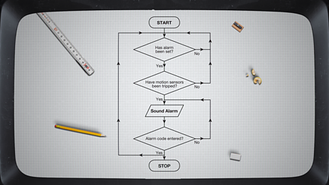
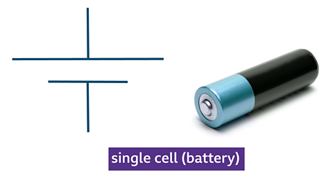
The simplest way I think to visualise the system is as a flowchart. Electrical control systems can be split into an input, process, output flow diagram. These are some common components that are found in electrical control systems.A battery. This provides the voltage to the circuit and drives the current. The longer line represents the positive terminal of the cell, and the shorter line represents the negative.
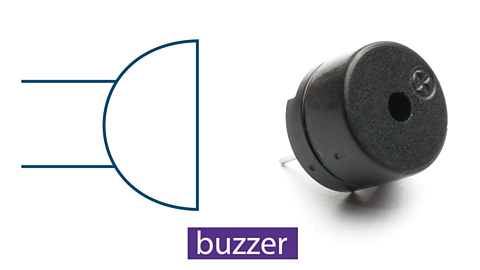
A buzzer. This is a simple output device that makes a sound once the circuit is complete and current is passing through it.An LED or light emitting diode. This is another example of a simple output device. The LED emits light when current is passing through it.Here is an example of a very simple electrical control system. It consists of a battery, a buzzer, and a switch. In this example, once the switch is pressed and the circuit is completed, the buzzer will sound. The straight lines connecting each component represent the wires. These allow the current to travel around the circuit. Simple circuit diagrams like this are used to create and test a circuit before physically creating it. Once this is completed, the next step is to create the PCB board.
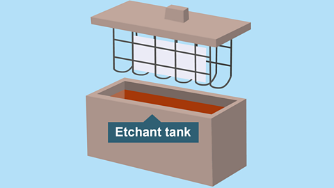
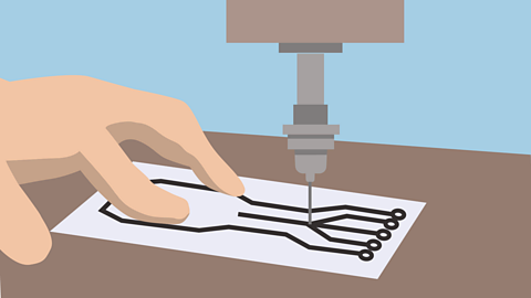
A PCB or printed circuit board is made from a non-conductive material with conductive lines printed or etched on it. Electrical components are then mounted on the board and soldered into place. The conductive lines connect the components together, creating a working circuit.This is an example of a simple printed circuit board. The green sections are made from the non-conductive material. The golden sections are made from a conductive material, copper and are what connects the components. PCBs are created on a computer and can then be printed ready to attach to the board.The copper layer is attached to the non-conductive material. Then, using a process known as etching, the copper is removed from all areas not required for the PCB. This will leave just the copper tracks which conduct the current between the components and the copper pads. The next step is to simply drill holes in each of the pads. These holes are where each of the components will be placed, ready to be soldered. The final step is then soldering each of the components in place. Once you attach the power source, you should now have a functioning circuit. These have been some simple examples, but many electronic circuits created in the same way make up much of what our modern world is built around.
SANDY
Are you actually taking notes? I thought you knew all of this.Wait a minute. Are you the fast and the curious?
JOE
What? No. That’s crazy.
That’s the end of the episode, bye.
Conductors and insulators
Conductors
Most metals allow A flow of electrical charge through a material. to flow through them easily because they have a low How difficult it is for current to flow. The more resistance there is, the harder it is for current to flow..
The process of electrical current flowing through a wire is called The process by which electrical current flows through a wire or another conductor., and materials that conduct are called conductors.
Insulators
Most non-metals, like plastic, glass and rubber do not allow A flow of electrical charge through a material. to flow through them easily.
They have a high How difficult it is for current to flow. The more resistance there is, the harder it is for current to flow. and are called insulators.
Non-metals are usually poor The process by which electrical current flows through a wire or another conductor. because they have very few free electrons. This makes it difficult for electrical current to flow through them. Insulators are materials that don’t allow an electrical current to flow through them.
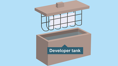
Making a printed circuit board (PCB)
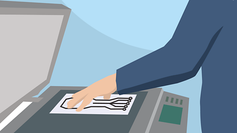
Image caption, Copy
Photocopy or trace a copy of the circuit onto an acetate sheet to make a mask of the circuit. This is called the PCB Artwork.
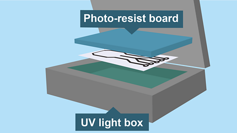
1 of 6

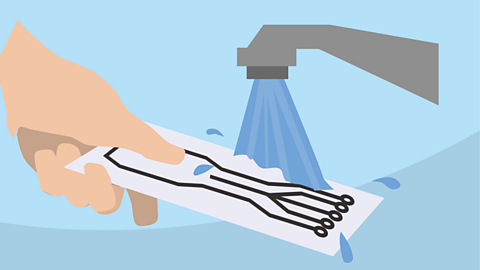
- Care is needed as a good PCB can be ruined by careless drilling.
- Once the holes are drilled the PCB can be populated and the components soldered in place.
Constructing a circuit diagram
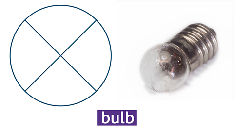
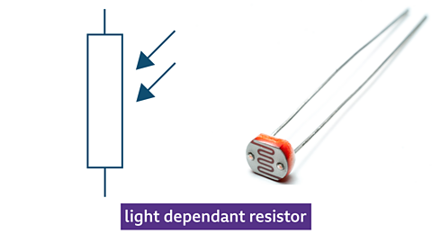
When constructing a circuit diagram, symbols are used to represent the different components, this makes it easier and quicker to draw rather than drawing detailed components.
Commonly used components and their symbols

1 of 9
Circuits can be drawn on the computer and symbols can be dragged onto a page and connected with lines. This allows the circuit to be tested before it gets made into a printed circuit board.
Basic electronic components
Electronic systems can be split up into three sections, these are:
Input → Process→ Output
Input
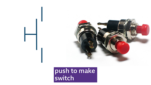
Input devices allow systems to understand changes in the environment around them. It is a device used to input data or information. A switch is an example of an input device.
Switches can be used to turn circuits on and off.
Example: A push-to-make (PTM) switch allows current to flow (or a signal to be passed on for processing) when pressed - therefore ‘making’ the circuit. A push-to-break (PTB) switch does the reverse and ‘breaks’ the circuit.
Process
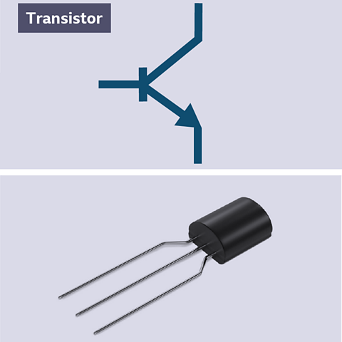
Process devices take the signal from the input stage of a system and act on it by changing it in some way.
Transistors are an example of a processing device, and are a special type of switch. When a small amount of volts is applied to the Base leg, a large current is allowed to flow from the Collector to the Emitter.
Output
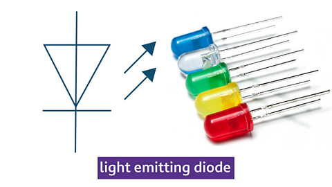
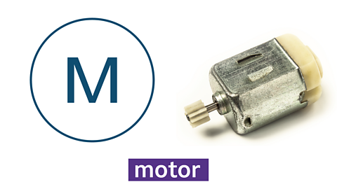
Output devices allow a system to present information back into the ‘real’ world. Examples can be seen everywhere, from car indicators to doorbell buzzers or lights. Examples of output devices include light emitting diodes (LED’s), buzzers and motors.
LED’s are the most common component used for producing light. The long leg is the positive (+) side, known as the anode, and the short leg is the negative (-) side, known as the cathode. If put into a circuit the wrong way round it will not work.
Resistors
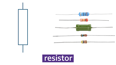
Resistors are another example of a processing device. Resistors are used to restrict the flow of current around a circuit and can prevent damage to components.
Resistors used in electrical circuits have a tolerance of how much power they allow into a circuit. When reading the value of a resistor, it must be held with the gold or silver band to the right - this is the tolerance band.
Band 1 = First Number
Band 2 = Second Number
Band 3 = Number of Zeros (Multiplier)
Band 4 = Tolerance
The amount of tolerance a resistor has is shown with the colour of the fourth stripe and is usually silver or gold.
Silver = +/- 5%
Gold = +/- 10%
Resistors in series:
Resistors are used to restrict the flow of current around a circuit and can prevent damage to components.
Resistors in series means that they are arranged in a way that is one after the other.
When calculating resistors in series the following calculation is used.
\(R_{Total} = R_1 + R_2\)
Potential divider rule
A voltage divider does as its name suggests - it divides a supply voltage across two resistors which are connected in series.
The supply voltage is divided in the ratio of the resistances in the voltage divider.
\({V} = \text{Supply Voltage} \times \frac{{{R_1}}}{{{R_1} + {R_2}}}\)
If one of the resistances in a voltage divider increases, then the voltage across that resistor also increases. This may appear to be the wrong way round but it is because of the way the resistors are connected together.
The circuit of a voltage divider may be drawn with the two resistors vertical, not horizontal. If there are two resistors in series across a voltage source, then the circuit is a voltage divider.
Question
A voltage divider consisting of two 500Ω resistors is connected across a 9V battery. Calculate the voltage across one of the resistors.
\({V_1} = {V_s} \times \frac{{{R_1}}}{{{R_1} + {R_2}}}\)
\(= 9\times\frac{500}{500+500}\)
\(= 9 \times \frac{1}{2} = 4.5V\)
Test yourself
Test yourself
More on Control systems
Find out more by working through a topic
- count3 of 5

- count4 of 5
- count5 of 5