Key points
- Power transmission involves transferring mechanical power from one part of a system to another
- Gear trains change the speed, direction, or torque between shafts. The gear ratio is calculated by dividing the number of teeth on the driven gear by the number of teeth on the driver gear
- An idler gear reverses the direction of rotation without changing the overall gear ratio
- Belts and pulleys transfer motion using continuous loops of flexible material. The velocity ratio is determined by dividing the diameter of the driven pulley by the diameter of the driver pulley
- A chain and sprocket system uses a chain looped around toothed wheels to transmit rotary motion. This system ensures no slippage, can transmit high torque, and is suitable for long distances between shafts
What is power transmission
Power transmission is how mechanical power is transferred from one part of a system to another. Understanding power transmission helps in designing efficient machines and solving mechanical engineering problems across various industries.
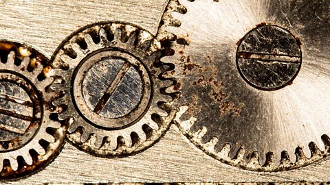
What are gear trains?
Simple gear trains consist of two or three gears attached to separate shafts. As one shaft rotates, its gear's teeth mesh with those of another gear, transferring motion to the next shaft. This system can change the speed, direction, and A measure of the force that can cause an object to rotate about an axis between shafts.

Found in everyday items like clocks and bicycles, gear trains can increase speed while decreasing force, or vice versa. Understanding how gears transfer motion between shafts helps explain the workings of many common machines and their importance in mechanical applications.
Smaller gears with fewer teeth turn faster than larger gears with more teeth. This difference in speed is called the gear ratio.
How to calculate gear ratio
\(\text{Gear ratio}=\frac{\text{number of teeth in the driven gear}}{\text{number of teeth in the driver gear}}\)
It shows how many times the driven gear rotates for each rotation of the driver gear.
Example:
The driven gear has 60 teeth and the driver gear has 20 teeth.
Gear ratio = teeth on driven gear / teeth on driver gear
Gear ratio = 60 / 20 = 3
- the gear ratio is 3:1
- the driven gear rotates once for every 3 rotations of the driver gear
Question
The driven gear has 50 teeth and the driver gear has 10 teeth.
Gear ratio = Teeth on driven gear / Teeth on driver gear
Answer
Gear ratio = 50 / 10 = 5
- the gear ratio is 5:1
- the driven gear rotates once for every 5 rotations of the driver gear
Idler gear
- an extra gear between the driver and driven gears
- main purpose is to reverses the direction of rotation
- doesn't change overall gear ratio
- freely rotates on its own shaft
Question
The driven gear has 30 teeth and the driver gear has 40 teeth. The idler gear has 20 teeth.
Gear ratio = teeth on driven gear / teeth on driver gear
Gear ratio = 30 / 40 = 0.75
- the gear ratio is 0.75:1 OR 3:4
- the driven gear rotates 3 times for every 4 rotations of the driver gear
- this represents a speed reduction
What are belts and pulleys
Belt drives are power transmission systems that use continuous loops of flexible material (belts) to transfer motion between two or more rotating shafts. They are widely used in various machines due to their simplicity, low cost, and ability to absorb shocks.

Each type has its unique advantages, making them suitable for different applications in mechanical systems:
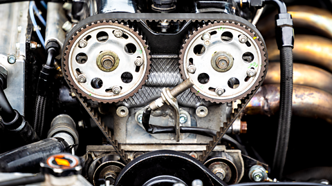
Toothed belts:
- have teeth that mesh with grooved pulleys
- provide positive drive with no slippage
- best for precise speed transmission
- common in timing belts of car engines
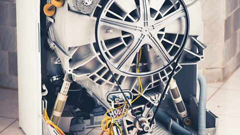
Round belts:
- circular cross-section
- simple and inexpensive
- work well for light loads
- often used in household appliances
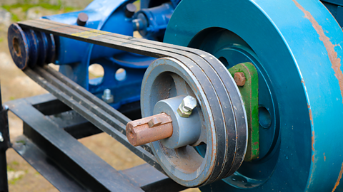
V-belts:
- V-shaped cross-section
- fit into grooved pulleys
- provide excellent grip and power transmission
- widely used in industrial machinery and vehicles
How to calculate the velocity ratio for belt drives
- similar to gear ratio, but uses pulley diameters instead of teeth numbers
- assumes no when a belt doesn't turn properly around a pulley the belt slips and power is lost (an ideal condition)
\(\text{Velocity ratio}=\frac{\text{diameter of driven pulley}}{\text{diameter of driver pulley}}\)
Example:
The driven pulley diameter is 300mm and the driver pulley diameter is 100mm.
Velocity ratio = diameter of driven pulley / diameter of driver pulley
Velocity ratio = 300 mm / 100 mm = 3
- the velocity ratio is 3:1
- the driven pulley rotates once for every 3 rotations of the driver pulley
- REMEMBER – a ratio greater than 1 indicates a reduction in speed of the driven pulley
Question
The driven pulley diameter is 200mm and the driver pulley diameter is 300mm.
Velocity ratio = diameter of driven pulley / diameter of driver pulley
Answer
Velocity Ratio = 200 mm / 300 mm = 0.67
- the velocity ratio is 0.67:1 OR 2/3
- the driven pulley rotates twice for every 3 rotations of the driver pulley
- REMEMBER – a ratio less than 1 indicates an increase in speed of the driven pulley
- consists of a chain looped around toothed wheels (sprockets)
- used to transmit rotary motion between parallel shafts
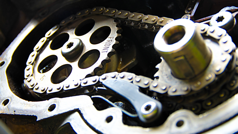
- similar to belt drives, but more robust and can handle heavier loads
- this mechanism combines the flexibility of belt drives with the non-slip properties of gears, making it versatile for various power transmission needs
Advantages:
- no slippage
- can transmit high torque
- suitable for long distances between shafts
Common applications:
- bicycles
- motorcycles
- industrial machinery
- conveyor systems
Test yourself
More on Mechanical control systems
Find out more by working through a topic
- count5 of 5
- count3 of 5