Key points
- Freehand sketching is the quickest way to capture initial design ideas on paper before they are forgotten, often done without rulers or templates.
- Annotation can be added to sketches to show key parts, sizes, materials, components, and construction, using shading, colour, and different viewpoints for clarity.
- CAD can help develop sketches and analyse how your design can be improved
- Models allow you to test if your solution woks and apply modifications
This section is relevant for students embarking on their design and manufacturing project and pursuing Option C: Product Design pathway.
Making use of freehand sketches
Freehand sketching is the quickest way of getting your initial designs on paper before an idea is forgotten. Freehand sketches are often done without a ruler or template and instead are produced quickly and freely.
Isometric drawings
Isometric drawings are commonly used in technical drawing to show an item in three dimensions (3D) on a page. Isometric drawings, sometimes called isometric projections, are a good way of showing measurements and how components fit together.
There are three main rules to isometric drawing:
- horizontal edges are drawn at 30 degrees
- vertical edges are drawn as vertical lines
- parallel edges appear as parallel lines
Isometric drawings are used to show a graphical representation of a 3D object. They are used by architects and engineers to communicate their ideas to the client and manufacturer, showing the product or design to The relationship between the real size of something and its size on a map, model, or diagram. Scale helps us represent big things in a smaller, more manageable size while keeping the proportions accurate..
How to us system and schematic diagrams
A block diagram that shows the inputs, processes and outputs of a system. and A diagram of an electronic circuit layout using graphical symbols to represent each component. are specifically for electronic and mechanical systems.
System diagrams
Designing certain products, e.g. electrical products, may require a different technique known as a systems approach. This logical approach is particularly useful in electronics where there is an input, process and output, as each stage has to perform a specific function before moving on to the next step.
Block diagrams can be written, usually in boxes, with the headings input, process, and output. When planning how a circuit will function, these headings are then used to plan what the input, process, and output could be.
In the case of designing an electric piano keyboard, the input is pressing the key, the process is generating the correct music note and the output is sound through the speaker. Systems approach should not be confused with schematic diagrams, which show how an electronic system should be connected together.
Systems approach flowcharts
A systems approach flowchart relates specifically to the design of a process. They can be used for programming a circuit so that a programmable chip can process an input and then turn on an output. Different shapes in a flowchart represent different types of operation, and these shapes have the same meaning worldwide.
Quality assurance decisions can also be added during the design process to ensure that problems are picked up and fixed within the system, e.g. a decision stage checking the dimensions of a part that has been manufactured.
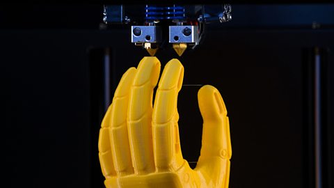
Modelling of design ideas
Modelling can be time-consuming and expensive, but a physical model allows a person to see and handle a product unlike viewing it on a screen through The process of creating a 2D or 3D design using computer software..
The manufacture of a part or product from a computer aided design (CAD) using computer-controlled machinery, such as a 3D printer. models made on a 3D printer using a CAD drawing are very accurate but also expensive, time-consuming and limited to 3D-printable materials.
Product designers can use easy-to-form and easily accessible materials, eg A very lightweight hardwood used for modelling., A low-density wood used for modelling. and cardboard, to create cheap models quickly and cheaply.
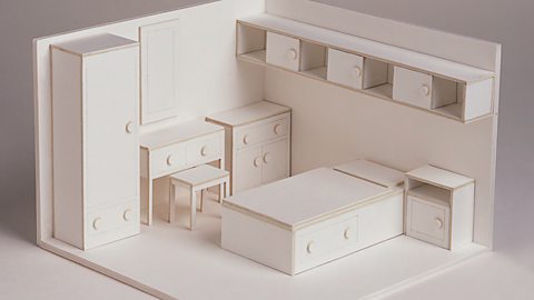
Models can be used to help:
- test the solutions functionality and whether the design is fit for purpose before selection for development and manufacture
- others, including a client, to see how the solution will look and provide feedback
- plan for manufacture, including suitable sizes and materials
Schematic diagrams
Schematic diagrams use symbols to show the layout of electrical or mechanicalsystems.
A circuit diagram is a schematic that shows how components are connected up.
Schematics can also be used in repair manuals. Symbols are simplified and look nothing like the physical components themselves, and the schematic diagram never makes a reference to the position of components on a circuit board.
The schematic diagram describes the points of electrical connection only, and these are shown as dots. The symbols are not drawn to scale so don’t have dimension information, and they can be spaced out to avoid looking jumbled or overly complex.
Producing a schematic drawing on a computer is far neater than drawing it by hand, with computer programs available to quickly create accurate and neat schematics that can be easily shared with others.
Reviewing your designs
Designers should review and compare their ideas to determine what design to take forward:
- review against the design brief
- review against the criteria in the design specification
- ask users for their opinions about the design ideas or models
- ask experts for their opinions about the design ideas or models
Analysis and evaluation are a crucial part in the design process as they can highlight any modifications that need to be made at the next stage. It is also a valuable point at which to consider the product against the original design specification and ensure the users’ needs are met.
Modifications will be made in relation to the design brief, specification and users’ needs to develop their ideas into successful products.
Creating drawings for manufacturing
Formal drawings
Formal drawings are a more precise style of drawing. They can be produced by hand or with computer aided design (CAD) packages.
Formal hand drawings use tools such as rulers and set squares to ensure accuracy and neatness.
Using computer aided design (CAD) allows the user to quickly make changes, and the drawings can be digitally shared and copied with ease.
Formal drawings are used when showing an idea to a client, showing measurements or getting feedback from a user group.
Bill of materials
The list of all the parts, materials, and instructions required to make a product
| Description | Materials | Part | Length | Height | Quantity |
|---|---|---|---|---|---|
| Top lid | Acrylic | 1 | 220mm | 200mm | 1 |
| Left side | Plywood | 4 | 321mm | 210mm | 2 |
| Front window | Acrylic | 6 | 200mm | 90mm | 1 |
| Front top | Plywood | 2 | 200mm | 101mm | 1 |
| Front | Plywood | 3 | 200mm | 120mm | 1 |
| Wheel | Plywood | 5 | 70mm | - | 4 |
| Back | Plywood | - | 200mm | 210mm | 1 |
Working drawings
Design and development involves creating working drawings and parts lists to enable a third party to manufacture the design. Working drawings are sent from a designer to a manufacturer to enable them to build a product.
Exploded diagrams
Exploded diagrams show how a product can be assembled and how the separate parts fit together, with dotted lines showing where the parts slide into place. The diagrams also show components that would usually be hidden in a solid drawing.
Exploded diagrams can take the place of detailed written instructions, meaning they can explain the construction of something without the barrier of different languages. They are widely used as instructions for self-assembly furniture.
Elevations
Elevations are the sides of an item you can see on the drawing, e.g. front elevation or side elevation. The top is referred to as the ‘plan’. These drawings enable detailed measurements to be added for every section of the product.
This isometric drawing shows the plan and front and side elevations of the shape.
- Horizontal lines should be drawn at a 30° angle
- Vertical edges should be drawn as vertical lines
- Parallel edges drawn as parallel lines
Orthographic projections
Orthographic projections are working drawings in either a first or third angle projection and show each side of a design. They are used to show an object from every angle to help manufacturers plan production.
Starting with a front view of a product, construction lines show where areas join and are used to draw a side and plan (top) view, ensuring that the drawing is accurate from all angles. These drawings are to scale and must show dimensions.
Third angle projections
Third angle projection is an accurate method to produce ‘working drawings’. The position of the plan, front and side views are important in this method of drawing.
In third-angle projection, the view of a component is drawn next to where the view was taken.
What you see from the right would be drawn on the right and what you see from looking at the top will be drawn above.
First Angle Projections
In first-angle projection, the view is drawn on the other end of the component, at the opposite end from where the view was taken.
Standard lines
Orthographic projections have a set of standard lines to show different aspects of the diagram. These lines allow complex shapes to be drawn simply in 2D.
Computer aided design (CAD)
Computer aided design (CAD) is the use of computer software to design new products in both in 2D and 3D. Some of the software commonly used in schools is 2D TechSoft and SolidWorks for 3D designs
CAD software allows you to easily visualise what a product is going to look like when it is made. The designs made on this software can be easily transferred to machines such as a laser cutter of 3D printer. This is known as Computer aided manufacture (CAM).
| Advantages of CAD | Disadvantages of CAD |
|---|---|
| Ideas can be drawn and developed quickly | Expensive to set up |
| Designs can be viewed from all angles and with a range of materials | Needs a skilled workforce |
| Some testing and consumer feedback can be done before costly production takes place | Difficult to keep up with constantly changing and improving technology |
| It becomes easier to design and test a range of ideas | Computers can fail |
Test yourself
Further study
Computer aided design (CAD) and Computer aided manufacture (CAM) revision-guide
Have a look at Computer aided design (CAD) and Computer aided manufacture (CAM)
What is the design process? revision-guide
Find out more about the design process.

How to control systems using a computer. revision-guide
Learn about the basics of flowcharts

More on Product design pathway
Find out more by working through a topic