Key points
- Push to make switch (PTM) is a momentary switch that closes the circuit only while pressed and is commonly used in doorbells and keyboards.
- Single pole, single throw switch (SPST) is a latching switch, either rocker or toggle, that connects or disconnects a single circuit and is used in power strips and light switches.
- Single pole, double throw switch (SPDT) is a switch, either toggle or slide, that connects one input to one of two outputs, allowing switching between two circuits, and is used in mode selection for small electronic devices.
- Reed switch is activated by a magnetic field and closes or opens a circuit when a magnet is near, commonly used in security systems and proximity sensors.
- Membrane switch is a thin, flexible switch with printed circuits, activated by pressing a designated area, similar to a PTM switch, and commonly used in keypads and control panels.-
In electronics, inputs are signals or data received by a process. These inputs can be either digital or analogue.
- Digital inputs: these signals have only two states, represented as 0 (off) or 1 (on) they are used in devices like switches, which can only be in one of two positions
- Analogue inputs: these signals can vary continuously within a range, typically from 0 to 255 they are used in sensors that measure varying conditions
You may want to refresh your knowledge on electrical components
Types of digital inputs
Push to make switch (PTM)
- momentary switch (it is only on when it is actuated or pressed)
- closes the circuit only while the button is pressed
- commonly used in doorbells and keyboards
- returns to the open position when released
Single pole, single throw switch (SPST)
rocker switch
- latching switch
- single pole, single throw (SPST) switch
- rocker mechanism to open or close a circuit
- commonly used in power strips and appliances
toggle switch
- latching switch
- single pole, single throw (SPST) switch
- connects or disconnects a single circuit.
- used in simple on/off applications like light switches.
Single pole, double throw switch (SPDT)
toggle switch
- single pole, double throw (SPDT) switch.
- connects one input to one of two outputs.
- allows switching between two circuits, unlike SPST version which only connects/disconnects one circuit.
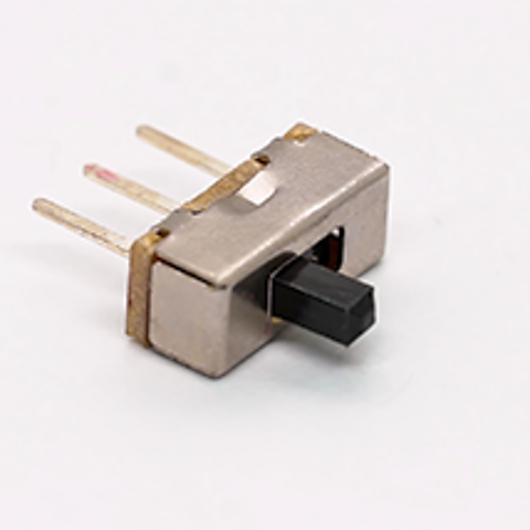
slide switch
- single pole, double throw switch (SPDT) switch
- slide mechanism to select between two outputs
- used in small electronic devices for mode selection
Reed switch
- activated by a magnetic field.
- closes or opens a circuit when a magnet is near.
- commonly used in security systems and proximity sensors
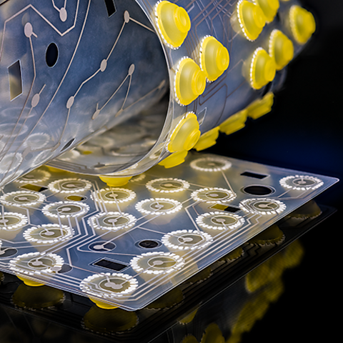
Membrane
- thin, flexible switch with printed circuits
- activated by pressing a designated area
- similar to a push-to-make (PTM) switch, closing the circuit when pressed
- commonly used in keypads and control panels for a low-profile, sealed interface
Types of analogue inputs
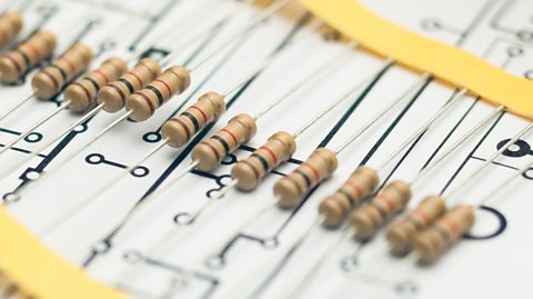
Light dependent resistors (LDRs)
- sensitive to changes in light levels
- resistance changes with light intensity
- used to create light or dark sensors
- can be used as an input
Thermistors
- sensitive to temperature changes
- resistance varies with heat levels
- used to create heat or cold sensors
- can be used as an input
Moisture sensors
- Measure moisture levels using two copper contacts
- Provide a range of values (0-255) based on moisture
- Used in agriculture for soil moisture monitoring
- Integrated into circuits for real-time moisture data
Variable resistors
- two-terminal device for adjusting current
- used to dim lights or control motor speeds
- changes resistance directly in a circuit
- different from a potentiometer, which adjusts voltage
- can be used as an input
How to read voltage/time graphs
Analogue voltage/time graph
These graphs show a smooth, continuous curve. The voltage varies over time without abrupt changes. For example, the voltage from a microphone or a temperature sensor would produce an analogue graph. The key feature is the infinite number of possible values within a range.
Digital voltage/time graph
These graphs display step-like changes, with distinct levels. The voltage switches between specific values, typically 0V and 5V, representing off/on binary states (0 and 1). An example is the pressing of a push to make switch (PTM). The graph looks like a series of square waves.
Test yourself
More on Electronic and microelectronic control systems
Find out more by working through a topic
- count5 of 12
- count6 of 12
- count7 of 12