Key points
- Different gears like spur, bevel, worm and wormwheel, rack and pinion, meshed gears, and threaded bars serve various purposes.
- When selecting a gear system, consider speed, direction, force, space, cost, and efficiency.
- Idler gears change the direction of rotation without altering the gear ratio and are used in timing belts, conveyors, and machine tools.
- Compound gear trains use multiple gear pairs for higher gear ratios, providing greater speed and torque changes.
- Understanding gear ratios, transmission speeds, and velocity ratios is essential for efficient gear system design.
What are gears?
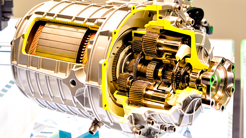
Gears are used to transmit motion and force from one part of a machine to another. Different types of gears are used for different applications.
Types of gears
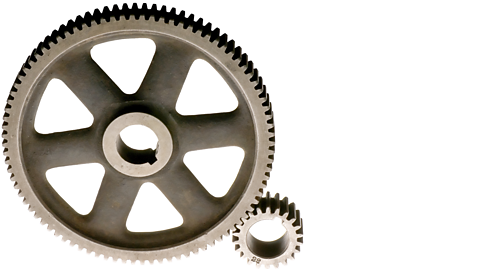
Spur gears:
These are the most common type of gear, used to transmit motion between parallel shafts. They have straight teeth and are easy to manufacture, making them a cost-effective choice for many applications.
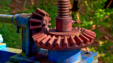
Bevel gears:
Bevel gears have teeth cut at an angle, allowing them to transmit motion between shafts that are not parallel. They are often used in applications where space is limited, such as hand drills and vehicles.
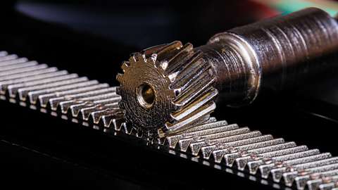
Rack and pinion:
This system converts rotary motion to linear motion or vice versa. It consists of a circular gear (pinion) meshing with a straight gear (rack), commonly used in steering mechanisms and machine tools.
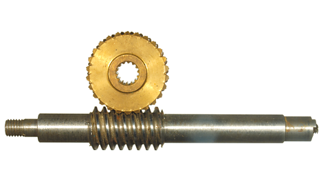
Worm and wormwheel:
This uses a screw-like 'worm' gear that meshes with a larger 'wormwheel'. It's good for transmitting motion between shafts at right angles and offers a high gear ratio, making it useful for applications requiring speed reduction.
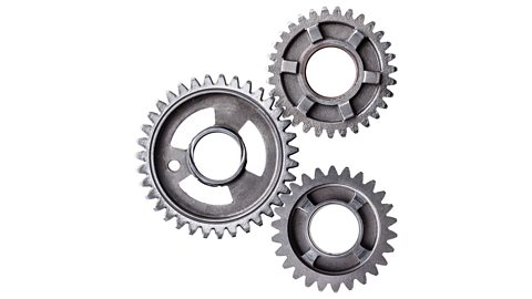
Meshed gears:
This general term refers to any gears that are interlocked or 'meshed' together to transmit motion. It encompasses various gear types, including spur gears, bevel gears, and others, depending on the specific configuration.
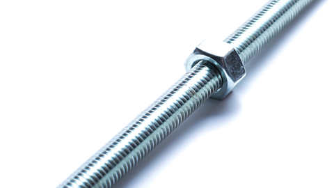
Threaded bar:
While not technically a gear, a threaded bar can transmit motion when combined with a nut. Rotating the nut causes linear movement along the bar, making it useful for applications like adjusting the height of objects or clamping parts together.
Selecting the appropriate gear system
Choosing the appropriate gear system depends on the specific needs of the design. Factors to consider include:
- Speed and direction: some gear systems increase or decrease speed, while others change the direction of motion. Bevel gears, for example, are often used to change the direction of motion by 90 degrees.
- Force: the amount of force to be transmitted is another consideration. Worm gears are known for providing high gear ratios, which can increase the force transmitted.
- Space: the amount of space available for the gear system can influence the choice.
- Cost: some gear systems are more expensive to manufacture than others.
- Efficiency: different gear types have varying levels of efficiency in transmitting power.
Designers and engineers carefully evaluate these factors to ensure they select the most suitable and efficient gear system for their specific application.
Idler gears
An idler gear is a gear positioned between the driver and driven gears in a gear train. Its primary function is to change the direction of rotation of the driven gear without affecting the gear ratio.
The role of an idler gear
In a simple gear train with only two gears, the driven gear always rotates in the opposite direction to the driver gear. By introducing an idler gear between the two, the direction of rotation of the driven gear is reversed, making it rotate in the same direction as the driver gear.
The idler gear does not change the overall gear ratio between the driver and driven gears. The number of teeth on the idler gear does not affect the speed or torque change between the input and output gears.
Applications of idler gears
Idler gears are used in various mechanical systems where it is necessary to maintain the same direction of rotation between the input and output shafts. Some common applications include:
- Timing belts: idler gears are used in timing belt systems to ensure the proper alignment and tension of the belt.
- Conveyors: idler gears are used in conveyor systems to change the direction of movement of the conveyor belt.
- Machine tools: idler gears are used in machine tools to change the direction of rotation of cutting tools or workpieces.
Compound gear trains
A compound gear train uses intermediate gears to connect the input and output gears, allowing for greater speed and torque changes compared to simple gear trains. They are essential in various machines, from power tools to vehicles.
Simple versus compound gear trains
- Simple gear train: consists of only two gears, an input (driver) gear, and an output (driven) gear. The speed and torque change is determined by the gear ratio, which is the ratio of the number of teeth on the two gears.
- Compound gear train: uses multiple gear pairs to achieve a higher gear ratio. Each pair of gears in a compound train can have its own gear ratio, and the overall gear ratio of the train is the product of the individual gear ratios.
Advantages of compound gear trains
- Higher gear ratios: achieve a greater speed reduction or torque increase compared to simple gear trains.
- Compact design: can achieve the same gear ratio as a simple gear train with fewer gears, resulting in a more compact design.
- Versatility: can be used to change the direction of rotation and provide different speed and torque combinations.
Compound gear trains are essential in various mechanical systems, providing the necessary speed and torque changes for efficient operation.
Calculations for compound gears
Understanding how to calculate gear ratios, transmission speeds, and velocity ratios, is crucial when working with gear systems.
How to calculate gear ratio
The gear ratio describes the relationship between the number of teeth on two meshing gears, influencing the speed and torque change between them.
Formula
\(\text{gear ratio} = \frac{\text{number of teeth on driven gear}}{\text{number of teeth on driver gear}}\)
- In a compound gear train with four gears, the driver gear (A) has 20 teeth and a driven gear (B) has 40 teeth, giving a gear ratio of 2:1.
- The second pair of meshed gears has a driver gear (C) with 30 teeth and a driven gear (D) with 60 teeth, also giving a gear ratio of 2:1.
- The overall gear ratio for the compound gear train is 4:1 (2:1 multiplied by 2:1), meaning the final output driven gear (D) turns a quarter as fast as the initial driver gear (A), or gear D turns once every time gear A turns 4 times.
Answer
A compound gear train has four gears: Gear A (driver) with 25 teeth, Gear B (driven) with 50 teeth, Gear C (driver) with 40 teeth, and Gear D (driven) with 100 teeth.
- Calculate the gear ratio for the first gear pair (Gear A and Gear B).
- Calculate the gear ratio for the second gear pair (Gear C and Gear D).
- Calculate the overall gear ratio for the compound gear train.
Question
- Gear ratio for the first pair: 50 teeth (Gear B) / 25 teeth (Gear A) = 2:1
- Gear ratio for the second pair: 100 teeth (Gear D) / 40 teeth (Gear C) = 2.5:1
- Overall gear ratio: \(\frac {2}{1} \times \frac{2.5}{1} = \frac{5}{1} = 5:1\)
How to calculate transmission speed
The transmission speed is the output gear's speed in a gear train, calculated using the gear ratio and input speed.
Formula:
\(\text{transmission speed} = \frac{\text{input speed}}{\text{gear ratio}}\)
Example:
If the input speed of a compound gear train is 200 RPM and the overall gear ratio is 4:1, then
\(\text{output speed} = \frac{\text{200 RPM}}{4}\)
= 50 RPM
Question
A compound gear train with four gears has an input speed of 1000 RPM. The gear ratios for the two gear pairs are 2.5:1 and 2:1.
- Calculate the overall gear ratio of the compound gear train.
- Calculate the transmission speed of the output gear.
Answer
- Overall gear ratio: 2.5:1 x 2:1 = 5:1
- \(\text{transmission speed} = \frac{\text{1000 RPM (input speed)}}{\text{5 (gear ratio)}}\)
= 200 RPM
How to calculate velocity ratio
The velocity ratio compares the speed of the driver gear to the speed of the driven gear.
Formula:
\(\text {velocity ratio} = \frac{\text{speed of driver gear}}{\text{speed of driven gear}}\)
Example:
In a compound gear train, if the initial driver gear rotates at 600 RPM and the overall gear ratio is 5:1, the final driven gear rotates at 120 RPM. Therefore, the velocity ratio is 5:1.
Question
A compound gear system has a driver gear rotating at 480 RPM. The gear train consists of four gears arranged in two pairs. The first pair has a gear ratio of 3:2, and the second pair has a gear ratio of 4:1.
- calculate the overall gear ratio of the compound gear system
- calculate the speed of the final driven gear
- calculate the velocity ratio of the compound gear system
- Overall gear ratio: 3:2 x 4:1 = 6:1
- Speed of the final driven gear = \( = \frac{\text{480 RPM (driver speed)}}{\text{6 RPM (gear ratio)}}\)
= 80 RPM - \(\text {velocity ratio} = \frac{\text{speed of driver gear}}{\text{speed of driven gear}}\)
\( = \frac{\text{480 RPM}}{\text{80 RPM}}\)
= 6:1
Test yourself
More on Mechanical and pneumatic control systems
Find out more by working through a topic
- count3 of 7

- count4 of 7
- count5 of 7
- count6 of 7